
Blog
Standard code calculations form the absolute foundation of mechanical engineering. Governing bodies, such as ASME and CSA, provide highly reliable mathematical formulas. Therefore, these basic rules work perfectly for standard shapes. If you build a basic cylinder or a simple sphere, standard math is completely sufficient.
However, real-world engineering projects frequently require highly custom designs. Sometimes, your design needs an intersecting nozzle at a strange angle. Other times, you must test a vessel head that faces extreme and rapid heat changes. In these specific cases, traditional calculations simply do not work.
As a result, professional engineers must rely on Finite Element Analysis for complex geometries.
In this comprehensive guide, we will explore exactly why standard codes fail for custom shapes. Next, we will break down the exact physics of stress concentrations. Finally, we will show how Finite Element Analysis (FEA) keeps your industrial equipment safe, cost-effective, and fully compliant with strict Canadian regulations.
The Core Limits of Standard Code Calculations
First, we must deeply understand how standard engineering codes actually work. Codes like ASME Section VIII Division 1 use a traditional method called “Design by Rule.”
This method relies on very basic formulas and extremely strict safety factors. If you want to build a standard pressure vessel, Design by Rule is fast. It is also very efficient for everyday manufacturing.
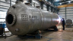
However, these rules make massive assumptions. They assume that your equipment has a standard geometric shape. Furthermore, they assume the internal pressure is perfectly uniform. If your design has unique physical features, these standard rules force mechanical engineers to guess.
Unfortunately, this guessing leads to three major industrial problems:
1. The Cost of Over-Engineering
When engineers use standard codes for custom shapes, they must play it safe. To compensate for unknown stress variables, they make the material much thicker. Consequently, the final equipment becomes incredibly heavy. This extra weight requires more raw materials, which drastically increases the final manufacturing cost.
2. Hidden Structural Weak Spots
Standard algebraic formulas only calculate the average stress across a large area. Therefore, they completely miss tiny “hot spots” at sharp metal corners. These missed spots might seem harmless at first. However, they can easily cause the equipment to crack and fail over time.
3. Failed Regulatory Inspections
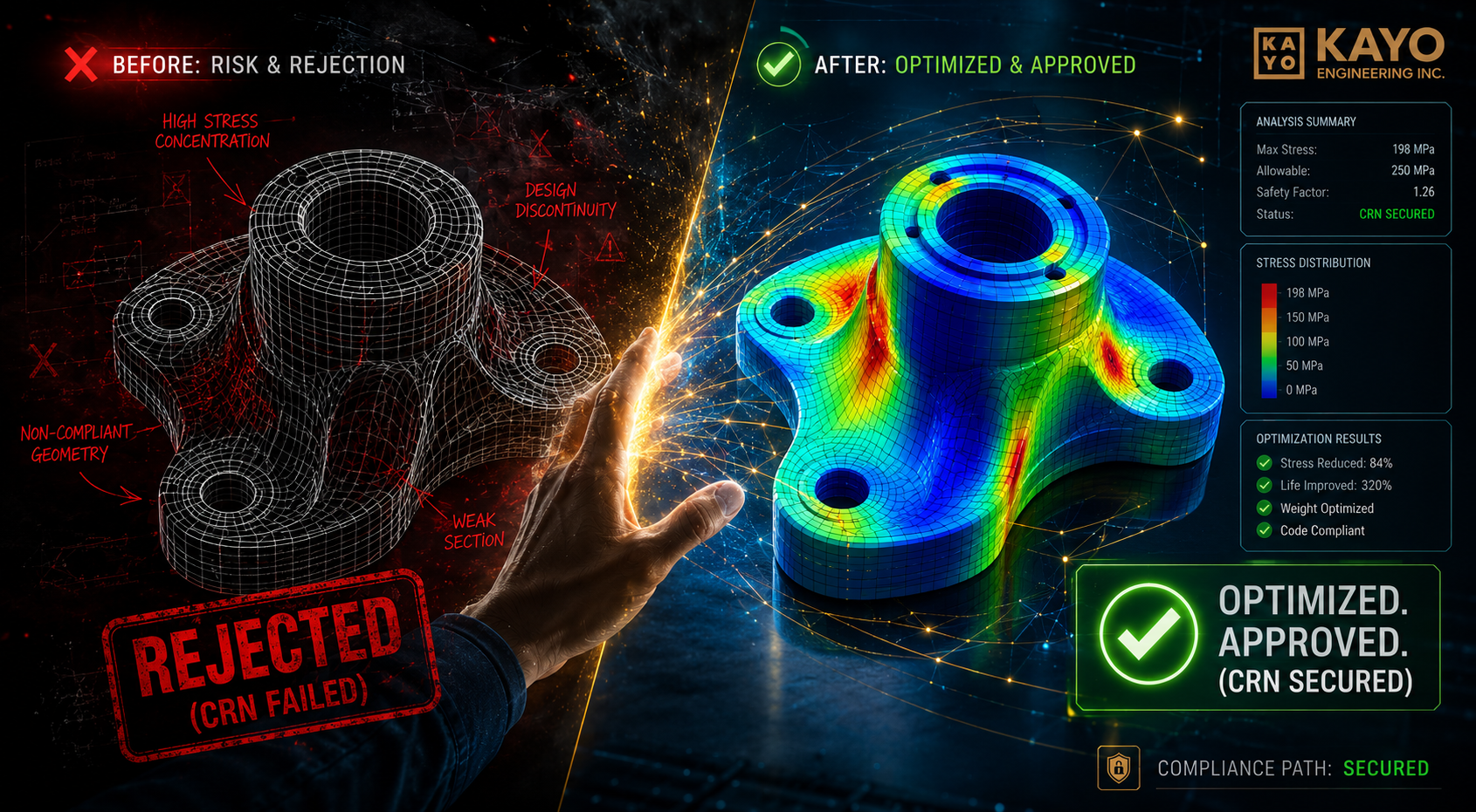
Regulators in Canada require strict, mathematical proof before issuing a Canadian Registration Number (CRN). If you use a custom shape without empirical proof, regulators like ABSA or TSSA will instantly reject your design.
Identifying Complex Geometries in Mechanical Design
In the mechanical design world, a geometry is complex if a simple formula cannot predict its internal stress. In short, if a physical shape stops the smooth flow of force, it is a complex geometry.
Common examples that require advanced FEA software include the following:
Non-Standard Nozzle Intersections
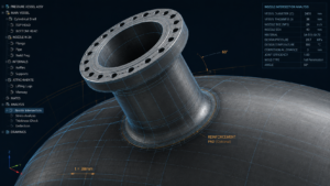
Nozzles are standard on almost all pressure vessels. However, non-standard nozzles create massive engineering challenges. For example, hillside nozzles intersect the main cylinder at severe angles. Similarly, placing two large nozzles very close together causes their stress zones to overlap. Standard math cannot calculate this overlapping stress safely.
Custom Vessel Transitions
Many industrial facilities have very tight spatial constraints. Therefore, engineers must design custom transitions. This includes parts that smoothly change from a rectangular shape to a round pipe shape. These weird transitions disrupt normal stress patterns.
Unique Structural Attachments
Vessels require support structures to stand upright. Custom lifting lugs, heavy trunnions, or unique support skirts create high-stress points on the main vessel shell. When the vessel is lifted or loaded, these attachments pull on the thin shell walls.
Engineered Leak Sealing Enclosures
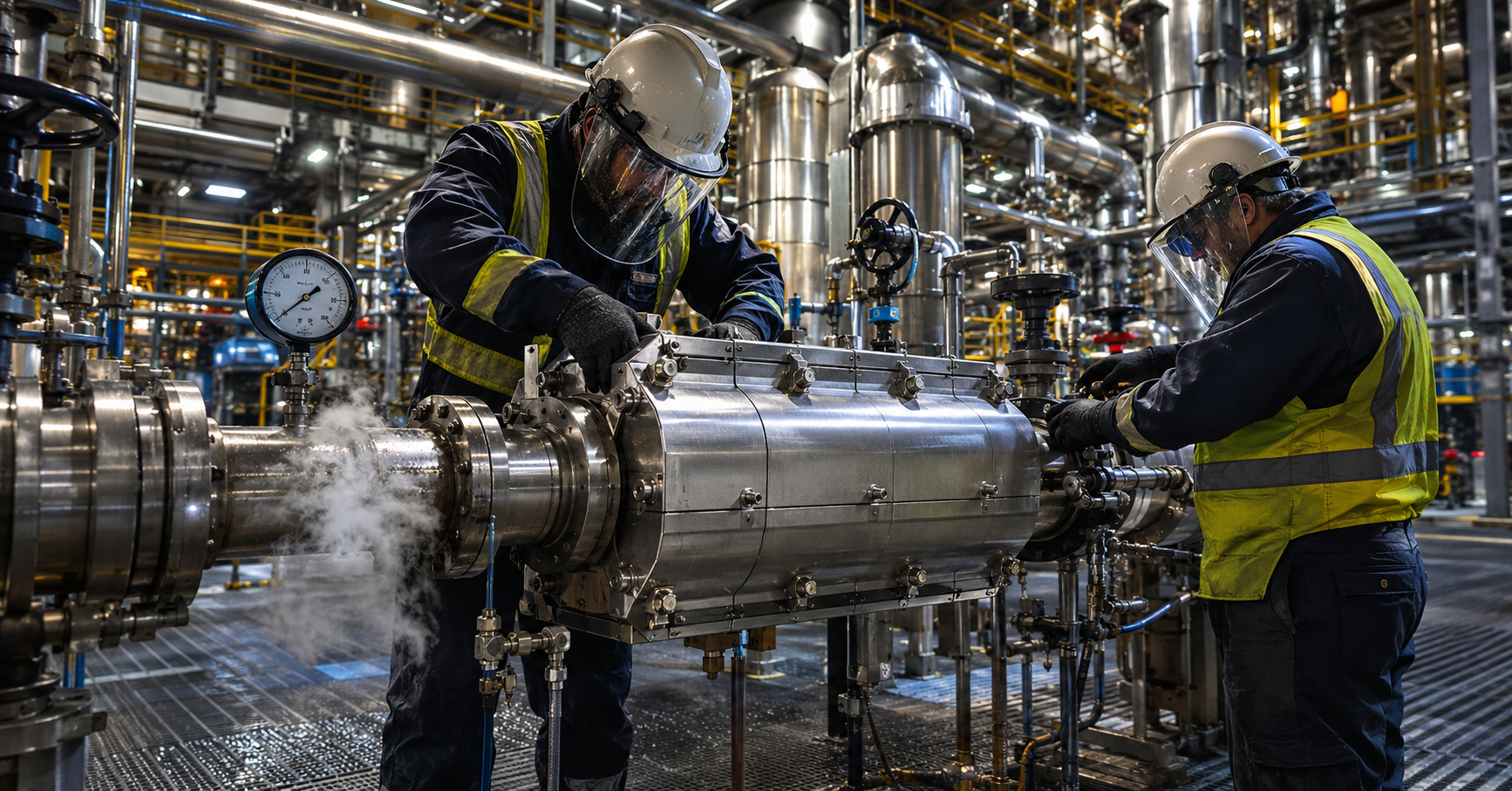
In heavy industry, pipelines often develop sudden leaks at the flanges. Shutting down the entire plant to fix one leak is too expensive. Therefore, engineers design custom leak-sealing clamps. These clamps must fit perfectly over the damaged, actively leaking pipe under high pressure. Because every leak is unique, every clamp is a highly complex geometry.
Because these shapes are so unique, they strictly require Finite Element Analysis for complex geometries to ensure total operational safety.
Understanding the Physics of Stress Concentrations
To truly understand FEA, you must first imagine how stress flows through solid metal. Think of stress flowing through a pipe just like water flowing down a river.
When a river is wide and straight, the water flows smoothly and calmly. This is exactly how stress moves through a standard, straight pipe. However, if you drop a large rock right into the middle of the river, the water violently crashes against it. The water is forced to speed up and divert around the obstacle.
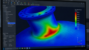
In engineering physics, a sharp corner acts just like that massive rock. It violently disrupts the flow of physical stress. As a result, the stress multiplies rapidly in a very tiny area.
Engineers call these specific areas “Stress Concentrations” or simply hot spots.
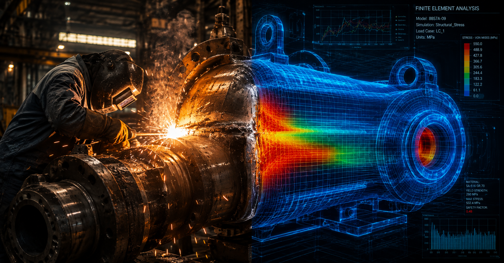
Standard mathematics cannot find these hot spots. In contrast, Finite Element Analysis breaks a 3D CAD model down into millions of tiny mathematical blocks. The software then calculates the exact stress inside every single microscopic block. Ultimately, this detailed process allows engineers to see exactly where the dangerous hot spots are hiding.
Primary vs Secondary Stress
When evaluating these hot spots, engineers look at different types of stress. Primary stress is the overall stretching of the vessel due to internal pressure. Standard codes handle this well.
However, secondary stress is the bending caused by geometric changes. Peak stress is the highest point of concentration at a sharp corner. FEA is the only tool that can accurately measure secondary and peak stresses in custom designs.
Solving Thermal Stress and Fatigue Failure
Equipment that faces rapid temperature changes is constantly at risk of breaking. In the engineering world, we call this fatigue failure.
For instance, consider what happens when metal gets hot. Naturally, the metal expands. If a complex custom design has thick metal sections connected directly to thin metal sections, a major problem occurs. The thin parts heat up and expand much faster than the thick parts.
Therefore, the metal literally fights against itself. This internal fighting creates massive thermal stress. Over time, as the equipment heats up and cools down every single day, tiny microscopic cracks begin to form at the transition points.
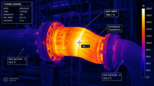
Thankfully, expert engineers use FEA software to map these precise temperature changes.
Calculating Lifecycle and Fatigue
First, the engineers input the exact operating temperatures into the software. Next, they program the heating and cooling cycles. The software then simulates 20 years of daily industrial use in just a few short hours.
The FEA results will tell the engineer exactly how many days the equipment will last before a crack forms. If the lifespan is too short, the engineer can change the metal thickness or adjust the corner radius. Ultimately, this allows the design team to fix the shape before the raw metal is even purchased.
Real-World Applications of FEA in Industry
Finite Element Analysis for complex geometries is used across many heavy industries. Here are three common real-world applications where FEA saves money and prevents disasters.
1. Heat Exchanger Tube Sheets
Heat exchangers are massive vessels filled with hundreds of tiny tubes. The plate holding all these tubes is called a tube sheet. Because it is full of holes, it is a highly complex geometry. FEA ensures the tube sheet will not bend or break under extreme fluid pressure.
2. High-Pressure Storage Tanks
Storage tanks holding dangerous chemicals must never fail. Sometimes, these tanks need custom access doors or unique mounting brackets due to space limits. Engineers use FEA to ensure these custom additions do not weaken the main tank structure.
3. Pipeline Repair Clamps
As mentioned earlier, online leak sealing is critical for refineries. A custom clamp must hold back extreme pressure while injecting a heavy sealant compound. FEA guarantees that the custom repair clamp will not explode during the delicate installation process.
The Complete Step-by-Step FEA Workflow
Finite Element Analysis is an incredibly powerful and highly advanced mathematical tool. However, there is a golden rule in FEA: “Garbage In, Garbage Out.” If the input data is wrong, the final colorful stress map will also be completely wrong.
Therefore, professional engineering firms follow a very strict, multi-step process.

Here is exactly how experts analyze a custom mechanical component:
Step 1: Accurate 3D CAD Modeling
First, the engineer draws the complex component in a 3D digital space. They must be highly precise. However, they also strip away useless details. For example, they remove digital paint layers or tiny cosmetic scratches. These small details slow down the computer without changing the final stress results.
Step 2: Creating the Perfect Mesh
Next, they divide the 3D model into thousands of tiny mathematical blocks. This is called the mesh. The engineer must make the mesh very dense near sharp corners. A dense mesh catches the high stress concentrations perfectly.
Step 3: Applying Boundary Conditions
After meshing, the engineer tells the software how the part is anchored in the real world. They specify exactly where the part is bolted down to the concrete floor. They also show where the part is allowed to slide or expand naturally.
Step 4: Adding Environmental Loads
Next, they add all the physical forces to the digital model. This includes the internal liquid pressure. Furthermore, it includes outside forces like heavy wind, thick snow, or even seismic earthquake forces.
Step 5: Solving the Mathematical Equations
Finally, the engineer runs the solver. The computer calculates millions of complex mathematical equations simultaneously. This step can take several hours depending on the computer’s power.
Step 6: Code Evaluation and Reporting
Once the software finishes, the engineer carefully reviews the visual stress maps. They look for dangerous red zones. Most importantly, they check if the calculated stresses meet the strict ASME Section VIII Division 2 guidelines.
Common Mistakes in Finite Element Analysis
Because FEA relies heavily on software, inexperienced designers often make critical mistakes. Knowing these mistakes is vital for project managers.
The “Garbage In, Garbage Out” Problem
Many beginners trust the software blindly. If you enter the wrong material properties, the software will still give you a beautiful, colorful report. However, that report will be totally fake. Expert engineering judgment is always required to verify the computer’s output.
Using the Wrong Mesh Density
If the mathematical blocks (the mesh) are too large, the software will miss the stress hot spots completely. Conversely, if the blocks are too small everywhere, the computer will freeze. Finding the perfect mesh balance takes years of engineering experience.
Misunderstanding Boundary Conditions
If you tell the software a pipe is bolted tight, but in reality, it sits on a sliding support, your thermal stress results will be completely wrong. Accurate real-world boundary conditions are the secret to safe FEA.
The Business ROI of Finite Element Analysis
Many business owners worry that FEA engineering services are too expensive. However, investing in Finite Element Analysis for complex geometries offers a massive Return on Investment (ROI).
Saving Money on Raw Materials
Standard codes force you to over-engineer. By using FEA, you prove exactly how much steel you actually need. Consequently, you can confidently use thinner plates. Saving just a few millimeters of high-grade stainless steel across a massive vessel saves tens of thousands of dollars.
Speeding Up Manufacturing Times
Thinner materials are much easier to roll, cut, and weld. Therefore, your fabrication shop can build the equipment significantly faster. This reduces expensive welding labor costs.
Preventing Unplanned Plant Shutdowns
If a custom part fails in the field, the entire production plant must stop. The cost of a single day of lost production far exceeds the cost of a proper FEA report. FEA acts as an insurance policy against catastrophic equipment failure.
Passing the CRN Regulatory Process in Canada
In Canada, industrial pressure equipment must have a Canadian Registration Number (CRN) before you can legally turn it on. Provincial regulators take safety extremely seriously.
If your design uses a custom shape, standard ASME calculations will not protect you. The regulators will look at your design, realize it falls outside standard rules, and simply reject your application. This rejection causes massive project delays.
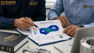
However, a professionally stamped FEA report solves this problem instantly. The report provides exact mathematical proof of safety. By showing the visual stress maps and highly detailed load data, you prove to the government that your custom design is safe.
As a result, you avoid expensive fabrication rework. Your project stays on schedule, and you get your CRN approved much faster.
Conclusion
Using Finite Element Analysis for complex geometries is never just about passing an inspection. Above all, it is a highly critical tool for industrial safety, material cost savings, and long-term mechanical reliability.
When standard formulas fail, FEA gives you the exact empirical answers you need. By replacing conservative guesses with real, advanced math, you can lower your overall manufacturing costs. Furthermore, you can confidently innovate and build much better equipment.
Need Expert Engineering Support?
At KAYO Engineering Inc., our team specializes in advanced mechanical analysis and pressure equipment design. If you currently face a complex geometric design challenge, or if you desperately need a stamped FEA report for your CRN application, contact our experts today. We provide dependable, innovative, and code-compliant solutions tailored just for you.
The Ultimate Guide to Securing a Canadian Registration Number (CRN) Without the Headaches
Introduction: Why CRN Approval Matters For OEMs, EPC contractors, manufacturers, and industrial facility owners, getting pressure equipment into service in
Industrial Equipment Modification: The Hidden Risks & Solutions
Upgrading your existing machinery seems like the ultimate cost-saving hack. But making structural changes without rigorous engineering validation? That transforms
Live Leak Sealing: Repair Pressurized Pipeline Leaks Without Plant Shutdowns
Every year, industrial facilities lose millions—sometimes billions across the industry—because of one preventable problem: unplanned shutdowns. Even a small leak